A summary of the hardware development of the battery management system
The development of new energy vehicles has been a basic consensus in the automotive industry, and is also highly valued by governments around the world. Power lithium ion battery has the characteristics of high energy density, high power density, long life and so on, and the cost has been declining continuously in the past few years. In the development of electric vehicle, the development of battery management system has become a core content. Its control object lithium battery has large capacity, many series nodes and complex system. As the power assembly unit of the core of automobile, the energy storage unit has high performance requirements, such as safety, durability, power, and so on. Managing and ensuring its safety is one of the bottlenecks affecting the popularization of electric vehicles. In order to ensure that the lithium ion battery works in the safe working range, it must be effectively controlled and managed through the management system to ensure the safety, durability and power of the battery. At the same time, the function safety characteristics, reliability and durability of the battery management system itself are the core of the automobile enterprises. A systematic review of the hardware development of the lithium ion battery management system for electric vehicles will be made.
battery management system definition and hardware classification
The main task of the battery management system is to ensure the design performance of the battery system, including:
1) perceive battery state: read the voltage, current and temperature information of battery monomer.
2) safety: according to the known status information, it can protect battery monomer or battery pack from damage and prevent safety accidents.
3) durability: make the battery work in a reliable design range, ensure the working temperature and SoC interval, and prolong the battery life.
4) power and power: maintain the battery's charge and discharge power when it meets the requirements of the vehicle.
From the hardware structure, the battery management system consists of the sensor, the controller, the actuator, the high voltage wire beam and so on. From the hardware structure, it has the following functional modules:
1) battery parameter detection (sensor layer): the total voltage of the battery system, the total current, the detection of the cell voltage of the single cell, the temperature detection, the smoke detection, the insulation detection, the collision detection and so on.
2) the contactor control and battery safety protection (executive layer): the battery management system has the circuit to drive the contactor and the actual state of the various high-voltage nodes of the diagnostic contactor. The last means of battery management is to disconnect the contactor. After the diagnosis of the fault, it is classified according to the damage of the fault, and the whole vehicle controller is notified by the serial network to handle effectively. In extreme case, the BMS can cut off the main circuit power and prevent the crew from violating the battery safety target. Injure.
3) MCU computing core: this part is the algorithm of the entire battery management system, and this part is also the basic circuit structure of the battery system as a vehicle controller to achieve the established functional security goals.
4) fault circuit: this part is about the processing of the whole battery management system itself and the external conditions, including fault detection, fault type judgment, fault location, fault information output and so on. Fault detection means using diagnostic algorithm to diagnose fault types by collecting sensor signals.
5) equalization circuit: the inconsistency of the entire battery system directly affects the actual capacity of the battery system, and this inconsistency will accumulate over time. The battery balance circuit and the corresponding control algorithm are based on the cell information of the single cell, using the equilibrium mode, as much as possible to make the battery capacity close to the capacity of the smallest monomer.
6) power management circuit and EMC suppression: the battery management system drives from the battery module and the 12V battery, and controls the power supply of the different nodes through a reasonable protection circuit. Because the battery system is in a high voltage and large current environment, the external load will lead to a large number of transient components on the bus, and the battery management system within the battery system needs to have good electromagnetic interference resistance.
7) network communication and wake-up circuit: the battery management system needs to communicate with the whole vehicle power assembly, body network and other vehicle network nodes, and also needs to carry out the corresponding network management and wake up the sleep management. In the whole battery life cycle, brushing and writing configuration, on-line calibration, monitoring, upgrading and maintenance are needed, and the general battery management system includes a multichannel serial communication network.
8) information storage unit: it is used to store key data, such as the situation that the customer uses throughout the life cycle, and this part of the core is to record the time and frequency of the battery system over the expected abuse of data.
9) other auxiliary circuits: the clock module and other circuits will be considered in the actual design.
10) optional circuit: the battery management system can add insulation detection circuit.
As shown in Figure 1, in order to complete a large and complete battery management system on a circuit board, the complexity of hardware and software, especially the high and low mixture, is more prominent, and the peripheral high and low wire harness makes the whole battery management system difficult to implement in the hardware design.
2 battery management system hardware and architecture development at home and abroad
It is precisely because of the above reasons that in the process of design, there are several practical design paths in the process of design, and two kinds of centralized and distributed structures are mainly used in hardware structure and function allocation. The centralized battery management system concentrates all the battery information measurements on a ECU, and then controls a lot of functions by the VCU, and the system carries out data acquisition, processing and state estimation in the battery tube. In the distributed battery management system, the most thorough is the battery system as a low-voltage ordinary ECU, the contactor control assembly, the battery voltage and temperature measurement unit intelligently, forming a more complex internal network of the serial network management.
2.1 centralized battery management system
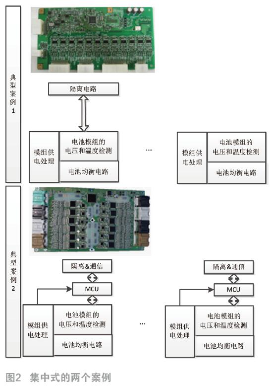
The centralized battery management system appeared earlier in the design of early electric vehicles, such as the typical case 1. The design can save cost and space. The whole communication process is mainly concentrated in the PCB circuit board, which is beneficial to the synchronous management of the signal collected by the sensor, and it is a very cost-effective scheme.
In the battery management algorithm, there is a substantial requirement for the sampling frequency and the real-time data analysis and processing of the battery. When the power output changes, the difference in time and the voltage of the single body also have synchronization problem, and the voltage and current also have time difference. This will directly affect the estimation accuracy of SoC and the analysis of the inconsistency of each monomer SoC. The system has different sampling frequency and synchronization requirements for different signals. The voltage and current signals change rapidly, and the sampling frequency and synchronization requirements are very high. In the centralized design, the greatest advantage is that the high speed of inter board communication can be used to ensure voltage synchronization. The voltage sampling time difference between the monomers in each collection plate is very small. The current sensor signal can also be collected by itself, and the CAN time frame is not needed.
The key point is to improve the acquisition chip ASIC, and have more consideration at the system level. So if case 2 often adds another MCU processing core to assist in detecting the state of ASIC, some signals are collected to form an additional diagnosis and signal management mechanism. It can be seen that the fault management mechanism and functional safety level are improving along with the improvement of the withstand voltage technology and the improvement of the internal computing unit of the acquisition chip ASIC.
The main disadvantages of centralized battery management system are as follows:
1) the design of the connector and the wiring harness is complex: as shown in Figure 2, the battery management unit has 6~8 connectors, and the corresponding sampling wire harness has a long line, making it necessary to measure and calibrate the error caused by the line pressure drop in the calculation process. The internal circuitry of the entire module also needs to consider the protection of the sampling line when short circuit and overcurrent occur in different sections.
2) the size, high voltage safety and installation of the circuit board: the overall size of the circuit board is large because of the centralized integration of high and low pressure. This is due to the need to meet the high voltage security needs to design enough safety space on the voltage difference to meet the design requirements of pressure resistance. This makes the battery system need to put forward additional requirements for the layout of the battery management system, limiting the generality of the layout, and is not conducive to the modular application of the battery system.
3) maintainability and reliability: because in hardware time accounting, the ASIC working time of the core fragment is long, it usually needs to consider the driving time (8000 hours) and the charging time (20000 hours), which makes the whole circuit need more power than most of the vehicle ECU times. A EMC environment with high and low voltage mixing and large current fluctuation poses great challenges to the life and reliability of the circuit. From the perspective of maintainability, hardware design is full of challenges.
2.2 distributed management
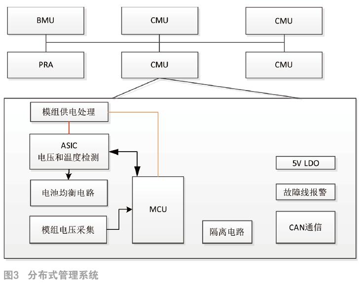
The other design direction is through modular design, the battery management master system (BMU) needs to complete the core algorithm function of battery management. The management function of the contactor is allocated to the relay management assembly (PRA), and the functions of the battery pack high voltage voltage acquisition, current acquisition, contactor drive and diagnosis, insulation detection and so on are completed. The battery information acquisition board (CMU) completes the acquisition, balance and temperature measurement of the single cell. The whole system consists of the battery management master system (BMU), the relay management assembly (PRA) and the battery information acquisition board (CMU) to form the internal serial communication network to form a subnet connection. The battery information acquisition board (CMU) is arranged on the power battery module, focusing on the security and anti-interference of the power supply end of the internal module and the 12 V power supply, and setting enough electrical stress redundancy in the power design to ensure stable and reliable work in the harsh environment.
Battery management
 From the hardware structure, distributed management system greatly simplifies the difficulty of the design, and realizes the consideration of modularization. It can be reused to a great extent on the PHEV/EV, and it has great applicability. Its shortcomings include:
1) in order to ensure the integrity of communication, it is necessary to do enough design at the network level, to implement anti-jamming design and time synchronization reference frame in the high-speed network of CAN to control the time difference of sampling data in each collection sub board. In the presence of strong interference, failure safety design is needed.
2) the cost is high and the layout needs to be considered in modules. Because each board is independent, the use link needs numbered and networking brushing program; in the module structure, the model can be built in and outside, not only the PCB, the cost of the shell also has a certain impact on the whole production process. The complexity of components makes it necessary for us to control each component's traceability and information management.
The SAIC battery management system has adopted a distributed hardware architecture on the hardware, and built a software development platform based on AUTOSAR+MBD on the software, and mastered the development ability of the BMS core algorithm. Fully modularized design of various functions is conducive to improving the development efficiency, reliability, portability and maintainability of software.
3 conclusion
With the reliability and security of the battery system, the hardware of the battery management system will play an increasingly important role. At present, the development of the domestic battery management system has shown a good trend. As an independent development body, the whole vehicle enterprise has developed the technology and products with its own characteristics according to the different requirements of the battery management system to meet the requirements of the electric vehicle. Because there is a technical problem between the battery and the battery management system, the battery management system has a lot of room for development. The in-depth intervention of the vehicle enterprises will make the combination of the two more progress.