A small scheme for lithium battery charger test
Lithium ion (Li+) batteries are more vulnerable than other chemical type batteries, and have very small tolerance for irregularities. Therefore, the lithium battery charging circuit is more complex, requiring high precision current and voltage settings. If these accuracy requirements can not be met, the charger may not be able to completely fill the battery, thereby reducing battery life or affecting battery performance.
In view of these requirements for Li+ battery chargers, it is very important to completely test the charger design and carry out segmented testing in the whole working range. However, it is very time-consuming to test the Li+ battery charger with conventional load (i.e. Li+ battery), and it is also difficult to achieve in laboratory and production environment. In order to simplify the test process, this paper gives a battery simulation circuit, which can speed up the test and test the charger of lithium ion battery without the actual battery.
CC-CV charging
The first stage of the lithium ion battery charging process requires moderate precision constant current (CC) charging, and then transition to high precision constant voltage (CV) charging at the second stage.
Figure 1 is the V-I characteristic curve of CC-CV integrated circuit (MAX1737) for lithium-ion battery charger. This type of IC is the core of all lithium-ion battery chargers in consumer products. The picture is clear
See CC (2.6V to 4.2V battery voltage) and CV (4.2V) area.

Fig. 1. the V-I curve of MAX1737 is the standard characteristic curve of Li+ battery charger.
When the battery is below 2.6V, different charging technologies are needed. If an attempt is made to charge the battery below 2.6V, the charger must provide a lower charging current ("conditioning current") and charge the battery voltage to 2.6V. This is a safety mechanism that must be taken when lithium ion batteries are discharged. Forced rapid charging at VBATT< 2.6V will cause the battery to enter the non recoverable short-circuit state.
The critical tolerance of the transition point from CC to CV is 40mV. The reason for such a strict tolerance is that if CV is too low, the battery will not be fully filled, and if CV is too high, it will shorten the service life of the battery. The termination of the charging process means that the battery is fully charged and the charger must be disconnected or closed. At the CV stage, when the charging current is reduced to a certain proportion of the fast charging current or the maximum charging current (normally < 10%), the charge is stopped.
Parameter test of battery charger for Li+ battery
The Li+ battery charger design usually consists of two basic parts: the digital part (the control state machine) and the analog part, and the analog part includes the current / voltage source with high precision (>1%) datum and accurate control. A complete test of the lithium ion charger (not only IC) is a very difficult and time-consuming task, not only to test the value of current or voltage.
When testing, the battery charger should be segmented in the whole working range: CC stage, switching from CC to CV, termination of charging, etc. As mentioned above, the ideal test is to use the conventional charger's load: Li+ battery. However, because the charging process takes an hour or even longer, it is time-consuming to use lithium batteries for testing. According to the different test conditions, such as large capacity battery + slow charging, small capacity battery + fast charging and other possible combinations, the test time is not the same.
In addition, the charging process can not improve the charging current on the premise of ensuring that the battery is not damaged, because the charging current is restricted by the maximum charging rate of the battery, that is, the fast charging current. For batteries commonly used in consumer products, it is seldom specified that the current is greater than 1C (the current that will discharge the battery completely within 1 hours). Therefore, in most cases, the time required to complete the charging cycle usually exceeds two hours. If repeated tests are needed, the battery needs to be discharged completely. This process is only a little shorter than charging. Alternatively, batteries with full discharge must be available at any time.
In addition, a simulated ideal load can be used to replace the real battery for load test. The DC response and dynamic stability of the circuit should be verified in simulation. However, it is very difficult to simulate the battery using the standard load used in power test. Unlike most load tests used in power tests, batteries can not simply be used as resistors or fixed current. As mentioned above, segmental testing must be carried out throughout the scope of work. The Li+ charger test circuit described below fully meets these requirements.
Select the battery model load
We first discuss two modeling methods that must be considered but eventually abandoned. One way of modeling the battery load is to use a voltage source with the capacity of the source (discharge) and the inhalation (charging) current in series with the resistance representing the battery internal resistance. Because the Li+ battery requires precise control of termination voltage and charging current, all Li+ chargers are actually regulated power converters.
In addition, because the stability of the voltage regulator (charger) depends on the dynamic characteristics of the load (battery), a load that is very similar to the model must be selected. Otherwise, the test can only verify the V-I characteristics of the charger itself.
If only a single test is done, a parallel voltage regulator can be used in series with the resistance, which is enough to simulate the internal resistance of the battery, and this simple battery model can fully meet the test requirements. The advantage of this method is that it is powered by the charger itself. However, more rigorous testing requires more accurate models. The internal voltage source is used in the model, and the voltage value is the function of supplying the total charge of the battery during charging.
When the battery is charged with constant current source, the voltage will change continuously and rise at a positive slope. This is due to the gradual decrease of the polarization ions accumulated around the cathode of the battery due to the chemical changes in the discharge and other batteries. Therefore, the working point of the charger depends on the length of the battery connection and the working history of the battery. It is difficult to simulate the load of complex models by constructing load with common devices that most electronic laboratories can find.
The battery that accurately simulates the charging process is very useful when testing the charging circuit frequently, or describing the circuit characteristics in detail. The simulation process requires continuous scanning of all DC operating points of the charger. Analog circuits also display results, enabling operators to find problems, failures and disturbances. If analog circuits can provide battery voltage output and signal, these results can be used directly as an oscilloscope signal. The test speed can be accelerated (from a few hours to tens of seconds) and can be repeated many times as needed, much more convenient than using real battery tests. However, the accelerated testing speed is unfavorable to determine the thermal effect of the charging power supply. Therefore, additional long time tests may be required to match the thermal time constant of the charging power supply and the regulating circuit.
Set up the battery model load
The single section lithium ion battery is simulated in Figure 2 circuit. The termination charge voltage of the charger CC phase and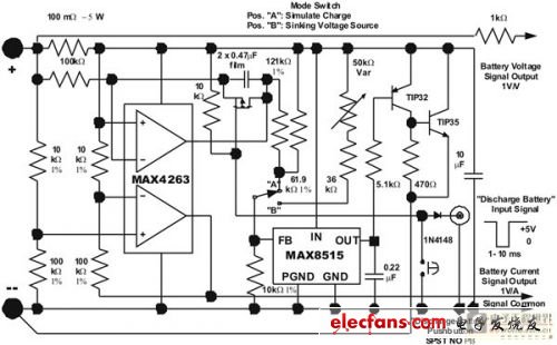 Fig. 2 a simulation circuit for single Li+ battery charging, which can test Li+ battery charger without using real battery.
The parallel voltage regulator is designed with a MAX8515 shunt voltage regulator and a pair of bipolar power transistors (the precision of the internal reference voltage is taken into account when selecting the voltage regulator). The large current TIP35 transistor is installed on the radiator that can dissipate the heat of the 25W.
One of the amplifiers of the MAX4163 dual operational amplifier is used to integrate the charging current. The other amplifier amplifies and bias the current measurement signal. The op amp has a high PSRR and can support full swing input / output range, simplifying the design of two functional circuits. Note that the 0.100 ohm current resistance, which is in series with the positive end of the battery emulator, is also used as internal resistance of the battery.
When working in a system with automatic test data collection function, the analog battery can be reset to full discharge state by external signals. In addition, when you manually test the settings, you can reset the keys.
Single pole single throw switch can be used to select two working modes of the simulated battery. When the A terminal is thrown, the integral charging simulator is implemented, as mentioned above. When the B terminal is thrown, the simulator will be set at a fixed DC operating point to test the output voltage and current of the charger when it is tested in the field. To achieve this function, the "setting" voltage can be manually adjusted between 2.75V and 5.75V by changing the 50K ohm variable resistor. These setting voltage values are related to the internal suction current. The measured voltage (VBATT) at the simulator is equal to the set voltage plus the voltage drop produced by the internal resistance (0.100 Ohm) of the simulated battery. The power source of the simulation circuit is from the battery charger output.
Performance of simulation circuit
Fig. 3 is a typical V-I waveform obtained from simulating lithium ion battery charging to 4.2V. Two test procedures can be seen from the diagram: one is charging the initial fast charging current of 1A (B and D), the other is charging with 2A fast charging current (curve A and C). In these two cases, the charge is first entered into the CC stage until the battery voltage reaches the termination voltage of 4.2V. After this, the current decays exponentially, while the voltage of the emulating battery remains unchanged. When the charging current is 2A, the time required to reach the termination voltage is shorter than the expected design. However, please note that doubling the current does not reduce the charging time by half. It only reduces the time of reaching the CV mode by half, which is the same as that of the real battery load.
Figure 4 is the V-I curve of two different settings of voltage: 3V and 4.1V. The dynamic resistance of the two curves (expressed in slope) is only the internal resistance of the battery simulated by 0.100 ohm resistance.Figure 3 Figure 2 plotted according to the battery simulation circuit of Figure 2. The fast charging waveform shows the operation of battery charger under two conditions, the CC phase provides the charging current of 1A (curve B and D) and 2A (curve A and C).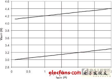
Fig. 4 Fig. 2 the suction current of the circuit when the voltage is 4.1V (upper curve) and 3V (lower curve), and the slope in two cases represents 0.1 ohm internal resistance.
It will be time-consuming and often unrealistic to test lithium battery charger using actual load due to the charging process of lithium ion batteries for an hour or longer. In order to speed up the battery charger test, this paper introduces a simple circuit to simulate lithium-ion battery. The circuit provides an effective way to test lithium battery charger without using real battery.